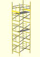
Beacon4 will be the fourth incarnation of the flagpole beacon (after Beacon2 and Beacon3), for Burning Man 2012. This year the plan is to take a different approach, and light the entire scaffold tower rather than just a beacon on top of the flagpole.
Project Status
- 2012-08-21: Fixed StrichLux C board set (bad soldering on a level shifter on an IO-SPI shorting out a power rail), found the slow refresh rate bug was actually VMware Fusion dropping UDP packets on my laptop, won't be an issue on the real thing as there's no VMware.
- 2012-08-20: Shipped all cabling, all LED strips (except the 1m test strip S33), StrichLux A and B, and the PC box w/ PC. StrichLux enclosure C shipped but the board set is still here to try to get it fixed/working properly, and to try to fix the slow refresh rate bug. Woot!
- 2012-08-19: Another 12h workday. All cabling terminated, all boards populated, all PWR-DC5s working well enough to use. StrichLux C's CORE board seems to not work, as the system sends no data out. Partial system was set up with StrichLux A and B and sort of worked, excep the refresh issue on higher channel numbers is still there and makes 3/4 almost useless. Supposed to ship tomorrow, but I don't see how it can.
- 2012-08-18: Epic workday. All PWR-DC5s done (but one channel on one not working yet), connectors added to the 2 COREs that didn't have them and all IO-SPIs that didn't have them, all feeders, jumpers, and strips labeled, all feeders except two connectorized, power feeders purchased and connectorized.
- 2012-08-17: Signal wiring terminated, but not yet inserted into the Mini-Fit plastic shells.
- 2012-08-15: Foam cut to fit, Sabres terminated.
- 2012-08-14: All in-box high power connectors are terminated except Sabre-side of the inputs. Tomorrow will get signal wiring terminated and all wiring installed in boxes.
- 2012-08-13: All connectors mounted on the 3 StrichLux boxes. Wiring of B and C still needs to be done.
- 2012-08-12: All LED strip now cut/terminated/sealed. Test of StrichLux A channels 1-3 are working mostly, though each higher numbered channel seems to refresh slower than the one before it. More troubleshooting will need to be done.
- 2012-08-11: StrichLux A enclosure has all connectors mounted and wired up (except only 1/2 of the power connector so far).
- 2012-08-06: 35m of LED strip cut/terminated/sealed.
- 2012-08-05: Reels A-I marked for cutting, so far all measurements add up correctly. Plan for tomorrow is to pick up StrichLux C enclosure, customize it, and get all LED strips terminated.
- 2012-08-04: All LED strip wire cut, terminated, and inserted into connectors. StrichLux B enclosure has all connectors drilled. Thermal tests failed running the PC inside a box, will need to add an external radiator.
- 2012-07-29: All feeders and jumpers now have female MX150Ls, and StrichLux A enclosure has output connectors drilled. Plan for tomorrow is to get the LED strip wire (832 inches total, ideally 208 inches/18 feet each of 4 colours) and get it cut into 4 inch pieces.
- 2012-07-28: 9 feeders connectorized with MX150Ls, power and Ethernet jacks installed in StrichLux A enclosure.
- 2012-07-25: All feeders and jumpers cut to length.
- 2012-07-24: Finalized all strip IDs and created an empty project in LightJams that has all fixtures added in their correct places. Built the other two required Core Boards and they power/program OK.
- 2012-07-23: Work on the installation helping system (BITS) is coming along, currently can scan a part and get a 3D model of where it goes. Inter-strip connectors, bulkhead M12 connectors, and Ethernet switch arrived. Cable ordered.
- 2012-07-19: fitPC is here!
- 2012-07-15: Ordered inter-strip connectors and remaining PWR-DC5, CORE, and IO-ETH parts.
- 2012-07-14: First successful end-to-end test of the whole StrichLux system driving 5m of LED strip from the PWR-DC5.
- 2012-07-11: Ordered the switch.
- 2012-07-09: Ordered the majority of enclosure connectors.
- 2012-07-07: First functioning test of StrichLux system driving 5m of LED strip.
- 2012-06-24: LED strips all obtained. Lighting design continues, as does firmware development.
- 2012-06-17: Hardware bring-up and firmware writing continuing. Lightjams is almost certainly going to be the software of choice. Lighting design is coming along.
- 2012-06-07: Work on StrichLux continues. Evaluated lots of software, Lightjams is looking the best at this point, though would require Windows.
- 2012-05-27: Completed rev. 1 StrichLux system design of all modules required for this project and sent all boards off for manufacturing.
- 2012-04-30: Started planning the power architecture for the project.
- 2012-04-29: Work continuing on IO-DMX module.
- 2012-04-24: Permission received!
- 2012-04-23: Requested permission from NeonBunny to attach LEDs to the tower.
- 2012-04-22: Started putting together idea.
Outstanding Issues
- How do we attach strips to toe boards?
- Can't ziptie/cable tie like we do everywhere else as the toe boards are wide
Ideas/Plans
- Main idea is to cover most of the scaffold tower in addressable LED strips, driven by multiple StrichLux modules
- Art-Net will be used between the controller and the StrichLux box
- Fit-PC 2i is being looked at to control the whole thing
- As nice as ARM would be power-wise, x86 will be much more flexible software-wise
- Need to make sure it will be powerful enough before we order
- Need to find a fanless very low power 4 or 5 port Ethernet switch
- Allied Telesis AT-FS705LE V5 might work, it's rugged, low power (1.5-2.5W), and cheap
- But it takes 7.5V which would be another regulator and is a potential point of failure that would bring the entire system down
- Alternative option is the GarrettCom S14H-Hi, it takes 8-15V in via screw terminals and is ruggedized, but $140 and draws 4W
- Best option may be the Sixnet SL-5ES-1, it's $100, rugged, takes 10-30VDC via screw terminals, and only draws 2W
- Ended up going with an M12 ethernet switch, the Octopus 5TX EEC
System Components
- Fit-PC 2i (controller)
- Octopus 5TX EEC 5-port Ethernet switch
- 3 StrichLux boxes (driver), each with:
- 60m of LED strips
- Power setup
- Debugging terminal (XO-1? Toughbook?)
Power Details
- Power requirements (peak)
- Fit-PC 2i - ???
- Ethernet Switch - ???
- StrichLux box(es) - ???
- LEDs - 10W/m (~1.8A/m at 5V measured, so 10W/m after losses is reasonable)
Power Architecture
http://www.asciiflow.com/#4007824742034929919/13747898[YOB-2]
                                                                              +--------------+
                                                                         +--->| LED Strip  0 |
                                                                         |    +--------------+
                                                                         |
                                                                         |    +--------------+
                                                       +---------------+ | +->| LED Strip  1 |
                                +--------------+       |               +-+ |  +--------------+
                                |              |       |   StrichLux   +---+
                                |     Dome     |    +->| Controller A  +---+  +--------------+
                                |   Lighting   |    |  |               +-+ +->| LED Strip  2 |
                                |              |    |  +---------------+ |    +--------------+
                                +--------------+    |                    |
                                        ^           |                    |    +--------------+
                                        |           |                    +--->| LED Strip  3 |
                             +----------+---------+ |                         +--------------+
                             |                    | |
                             |                    | |                         +--------------+
                             |                    +-+                    +--->| LED Strip  4 |
                             |                    |                      |    +--------------+
                             |                    |                      |
                             |                    |                      |    +--------------+
                             |                    |    +---------------+ | +->| LED Strip  5 |
    +---------------+        |                    |    |               +-+ |  +--------------+
    |               |        |    Distribution    |    |   StrichLux   +---+
    |    Battery    +=======>|                    +--->| Controller B  +---+  +--------------+
    |               |        |        Box         |    |               +-+ +->| LED Strip  6 |
    +---------------+        |                    |    +---------------+ |    +--------------+
                             |                    |                      |
                             |                    |                      |    +--------------+
                             |                    |                      +--->| LED Strip  7 |
                             |                    |                           +--------------+
                             |                    +-+
                             |                    | |                         +--------------+
                             +--+-------+---------+ |                    +--->| LED Strip  8 |
                                |       |           |                    |    +--------------+
                      +---------+       |           |                    |
                      v                 v           |                    |    +--------------+
              +--------------+   +--------------+   |  +---------------+ | +->| LED Strip  9 |
              |              |   |              |   |  |               +-+ |  +--------------+
              | Convienience |   |    System    |   |  |   StrichLux   +---+
              |   Outlets    |   |  Controller  |   +->| Controller C  +---+  +--------------+
              |              |   |              |      |               |   +->| LED Strip 10 |
              +--------------+   +--------------+      +---------------+      +--------------+
Lighting Layout
Random Notes
- Decided on 60m length total (3 StrichLux boxes)
- That's 1920 RGB LEDs and ~600W peak!
- Will need to come up with a lighting layout/design that will fit within this
Dimensions
Main Module (4 of these vertically, 2 of which will be lit)
-----------------------------------------------------------

+-----D-----+------E------+       |\                                   /|
|           |             |       |    \                           /    |
|-----D-----|             |       |        F                   /        |
|           H             |       |            \           /            |
|-----D-----|             |       |                \   /                |
|           |             |       |                /   \                |
|-----D-----+------E------|       |            /           \            |
|                         |       |        F                   \        |
A                         A       A    /                           \    A
|-----------B-------------+       |/                                   \|


Top Module
----------

|                         |       |                                     |
|                         |       |                                     |
|                         |       |                                     |
|                         |       |                                     |
|-------B-----------------|       |------------------C------------------|
|            |            |       |  /                               \  |
|            G            |       |------------------C------------------|
|            |            |       |                                     |
A============B============A       A                                     A
|                         |       |                                     |
- A - Module Height (5ft 1in)
- B - Module Width (5ft)
- C - Module Depth (7ft)
- D - Ladder Width (2.5ft)
- E - Beside-Ladder Width (B - D) (2.5ft)
- F - Cross-brace Length (7.37ft)
- G - Top Rail Support Height
- H - Ladder Section Height (3.5ft)
- n - Number of Modules (3)
- x - Number of Main Modules (2)
Idealized Layout
- Vertical Mains: A * 4 * n = 5.083 * 4 * 3 = 61ft (done piecing)
- Beside-Ladder Boxes: (E * 2 + H) * 2 * x = 34ft (done piecing)
- Cross-braces: F * 2 * 2 * x = 7 * 2 * 2 * 2 = 59ft (done piecing)
- Top Rail: B * 2 + C * 2 = 24ft (done piecing)
- Top-Middle Rail: C * 2 = 14ft (done piecing)
- Toe Board: B * 4 = 10ft (done piecing)
- Total: 202ft / 61.5m
Actual Layout
- Vertical Mains: 4.5m each * 4
- Cross brace tubes: 1.125m each * 8
- Toe board: 1.5m each * 2
- Top middle rail: 2.1m each * 2
- Top rail long side: 2.1m each * 2
- Top rail short side: 1.5m each * 2
- Ladder box vertical: 1m each * 4
- Ladder box horizontal: 0.75m * 8
- Total: 60.00m
Universe <-> Controller Mapping
Since physical locations of the controllers changed after all the channels were laid out, the universe numbers don't map linearly to the controller channels anymore.
- Controller A (Base of VM2)
- A-1 - U0
- A-2 - U1
- A-3 - U5
- A-4 - U6
- Controller B (Base of VM3)
- B-1 - U2
- B-2 - U7
- B-3 - U9
- B-4 - U10
- Controller C (Base of VM4)
- C-1 - U3
- C-2 - U4
- C-3 - U8
- C-4 - U11
LED Strip List
| ID
|
Piece
|
Location
|
Length
|
# of LEDs
|
Reel
|
Universe
|
DMX Channels
|
LightJams IDs
|
| S01
|
Vertical Main 1
|
Vertical Main 1
|
450cm
|
144
|
C
|
U0
|
1-432
|
BAA-BFN
|
| S02
|
Vertical Main 2
|
Vertical Main 2
|
450cm
|
144
|
D
|
U1
|
1-432
|
CAA-CFN
|
| S03
|
Vertical Main 3
|
Vertical Main 3
|
450cm
|
144
|
E
|
U2
|
1-432
|
DAA-DFN
|
| S04
|
Vertical Main 4
|
Vertical Main 4
|
450cm
|
144
|
F
|
U3
|
1-432
|
EAA-EFN
|
| S05
|
Cross brace tube 1
|
MF1/2 B Right
|
218.75cm
|
70
|
G
|
U4
|
1-210
|
FAA-FCR
|
| S06
|
Cross brace tube 2
|
MF1/2 A Right
|
218.75cm
|
70
|
G
|
U5
|
1-210
|
GAA-GCR
|
| S07
|
Cross brace tube 3
|
MF1/2 A Left
|
218.75cm
|
70
|
H
|
U6
|
1-210
|
HAA-HCR
|
| S08
|
Cross brace tube 4
|
MF1/2 B Left
|
218.75cm
|
70
|
H
|
U6
|
211-420
|
HCS-HFJ
|
| S09
|
Cross brace tube 5
|
MF3/4 A Right
|
218.75cm
|
70
|
I
|
U8
|
1-210
|
JAA-JCR
|
| S10
|
Cross brace tube 6
|
MF3/4 B Right
|
218.75cm
|
70
|
I
|
U9
|
1-210
|
KAA-KCR
|
| S11
|
Cross brace tube 7
|
MF3/4 B Left
|
218.75cm
|
70
|
J
|
U10
|
1-210
|
LAA-LCR
|
| S12
|
Cross brace tube 8
|
MF3/4 A Left
|
218.75cm
|
70
|
J
|
U10
|
211-420
|
LCS-LFJ
|
| S13
|
Toe board 1
|
1 (Close)
|
150cm
|
48
|
A
|
U11
|
349-492
|
MEM-MGH
|
| S14
|
Toe board 2
|
2 (Far)
|
150cm
|
48
|
A
|
U11
|
1-144
|
MAA-MBV
|
| S15
|
Top middle rail 1
|
Left
|
212.5cm
|
68
|
K
|
U11
|
145-348
|
MBW-MEL
|
| S16
|
Top middle rail 2
|
Right
|
212.5cm
|
68
|
K
|
U8
|
307-510
|
JDY-JGN
|
| S17
|
Top long rail 1
|
Right
|
212.5cm
|
68
|
L
|
U9
|
307-510
|
KDY-KGN
|
| S18
|
Top long rail 2
|
Left
|
212.5cm
|
68
|
L
|
U7
|
145-348
|
IBW-IEL
|
| S19
|
Top short rail 1
|
TF1
|
150cm
|
48
|
B
|
U7
|
1-144
|
IAA-IBV
|
| S20
|
Top short rail 2
|
TF2
|
150cm
|
48
|
B
|
U7
|
349-492
|
IEM-IGH
|
| S21
|
Ladder box vertical 1
|
MF1
|
100cm
|
32
|
A
|
U4
|
283-378
|
FDQ-FEV
|
| S22
|
Ladder box vertical 2
|
MF2
|
100cm
|
32
|
A
|
U5
|
283-378
|
GDQ-GEV
|
| S23
|
Ladder box vertical 3
|
MF3
|
100cm
|
32
|
B
|
U8
|
211-306
|
JCS-JDX
|
| S24
|
Ladder box vertical 4
|
MF4
|
100cm
|
32
|
B
|
U9
|
211-306
|
KCS-KDX
|
| S25
|
Ladder box horizontal 1
|
MF1 Top
|
75cm
|
24
|
C, D
|
U4
|
211-282
|
FCS-FDP
|
| S26
|
Ladder box horizontal 2
|
MF1 Bottom
|
75cm
|
24
|
E, D
|
U4
|
379-450
|
FEW-FFT
|
| S27
|
Ladder box horizontal 3
|
MB2 Top
|
75cm
|
24
|
K
|
U5
|
211-282
|
GCS-GDP
|
| S28
|
Ladder box horizontal 4
|
MF2 Bottom
|
75cm
|
24
|
L
|
U5
|
379-450
|
GEW-GFT
|
| S29
|
Ladder box horizontal 5
|
MF3 Top
|
75cm
|
24
|
G, H
|
U0
|
433-504
|
BFO-BGL
|
| S30
|
Ladder box horizontal 6
|
MF3 Bottom
|
75cm
|
24
|
I, H
|
U1
|
433-504
|
CFO-CGL
|
| S31
|
Ladder box horizontal 7
|
MF4 Top
|
75cm
|
24
|
J, H
|
U2
|
433-504
|
DFO-DGL
|
| S32
|
Ladder box horizontal 8
|
MF4 Bottom
|
75cm
|
24
|
F, H
|
U3
|
433-504
|
EFO-EGL
|
Reel Assignment
- Reel A (100% used)
- Toe Board 1: 150cm
- Toe Board 2: 150cm
- Ladder box vertical 1: 100cm
- Ladder box vertical 2: 100cm
- Reel B (100% used)
- Top short rail 1: 150cm
- Top short rail 2: 150cm
- Ladder box vertical 3: 100cm
- Ladder box vertical 4: 100cm
- Reel C (100% used)
- Vertical Main 1: 450cm
- Ladder box horizontal 1a: 50cm (chunk 1)
- Reel D (100% used)
- Vertical Main 2: 450cm
- Ladder box horizontal 1b: 25cm (chunk 2)
- Ladder box horizontal 2b: 25cm (chunk 2)
- Reel E (100% used)
- Vertical Main 3: 450cm
- Ladder box horizontal 2a: 50cm (chunk 1)
- Reel F (100% used)
- Vertical Main 4: 450cm
- Ladder box horizontal 8a: 50cm (chunk 1)
- Reel G (100% used)
- Cross brace tube 1: 218.75cm
- Cross brace tube 2: 218.75cm
- Ladder box horizontal 5a: 62.5cm (chunk 1)
- Reel H (100% used)
- Cross brace tube 3: 218.75cm
- Cross brace tube 4: 218.75cm
- Ladder box horizontal 5b: 12.5cm (chunk 2)
- Ladder box horizontal 6b: 12.5cm (chunk 2)
- Ladder box horizontal 7b: 12.5cm (chunk 2)
- Ladder box horizontal 8b: 25cm (chunk 2)
- Reel I (100% used)
- Cross brace tube 5: 218.75cm
- Cross brace tube 6: 218.75cm
- Ladder box horizontal 6a: 62.5cm (chunk 1)
- Reel J (100% used)
- Cross brace tube 7: 218.75cm
- Cross brace tube 8: 218.75cm
- Ladder box horizontal 7a: 62.5cm (chunk 1)
- Reel K (100% used)
- Top middle rail 1: 212.5cm
- Top middle rail 2: 212.5cm
- Ladder box horizontal 3: 75cm
- Reel L (100% used)
- Top long rail 1: 212.5cm
- Top long rail 2: 212.5cm
- Ladder box horizontal 4: 75cm
Cable Routing
- Overview
- When viewing the tower end-on with the ladder on the left:
- Vertical Main 1 is on the left of the close end
- Vertical Main 2 is on the right of the close end
- Vertical Main 3 is on the left of the far end
- Vertical Main 4 is on the right of the far end
- Main Frame 1 is the lower close frame of the 2 lit ones
- Main Frame 2 is the lower far frame of the 2 lit ones
- Main Frame 3 is the higher close frame of the 2 lit ones
- Main Frame 4 is the higher far frame of the 2 lit ones
- Top Frame 1 is the close top frame
- Top Frame 2 is the far top frame
- Cross Brace A are the tubes running low-to-high from MF1/3 to MF2/4
- Cross Brace B are the tubes running high-to-low from MF1/3 to MF2/4
- Toe Board 1 is the close board
- Toe Board 2 is the far board
- Controller A
- Channel 1
- Feeder (up VM1) -> Vertical Main 1 -> Long Jumper (via Toe Board 1, down VM2) -> MF3 LBH Top
- Channel 2
- Feeder (up VM2) -> Vertical Main 2 -> Long Jumper (down VM2) -> MF3 LBH Bottom
- Channel 3
- Feeder (up VM3) -> Vertical Main 3 -> Long Jumper (via Toe Board 2, down VM4) -> MF4 LBH Top
- Channel 4
- Feeder (up VM4) -> Vertical Main 4 -> Long Jumper (down VM4) -> MF4 LBH Bottom
- Controller B
- Channel 1
- Feeder (up VM4) -> CB MF1/2 B Right -> MF1 LBH Top -> MF1 LBV -> MF1 LBH Bottom
- Channel 2
- Feeder (up VM2) -> CB MF1/2 A Right -> MF2 LBH Top -> MF2 LBV -> MF2 LBH Bottom
- Channel 3
- Feeder (up VM1) -> CB MF1/2 A Left -> Short Jumper -> CB MF1/2 B Left
- Channel 4
- Feeder (up VM3) -> Short Jumper (via TF2 Top Short Rail) -> TF2 Top Short Rail -> Left Top Long Rail -> TF1 Top Short Rail
- Controller C
- Channel 1
- Feeder (up VM4) -> CB MF3/4 A Right -> Short Jumper -> MF3 LBV -> Long Jumper (via MF3 LBH Top, VM2) -> Right Top Middle Rail
- Channel 2
- Feeder (up VM2) -> CB MF 3/4 B Right -> Short Jumper -> MF4 LBV -> Long Jumper (via MF4 LBH Top, VM4) -> Right Top Long Rail
- Channel 3
- Feeder (up VM3) -> CB MF3/4 B Left -> Short Jumper -> CB MF 3/4 A Left
- Channel 4
- Feeder (up VM4) -> Toe Board 2 -> Left Top Middle Rail -> Toe Board 1
Feeders and Jumpers
- Feeders
- Feeder A-1 - 310cm (F01)
- Feeder A-2 - 310cm (F02)
- Feeder A-3 - 310cm (F03)
- Feeder A-4 - 310cm (F04)
- Feeder B-1 - 360cm (F05)
- Feeder B-2 - 360cm (F06)
- Feeder B-3 - 360cm (F07)
- Feeder B-4 - 711cm (F08)
- Feeder C-1 - 576cm (F09)
- Feeder C-2 - 576cm (F10)
- Feeder C-3 - 516cm (F11)
- Feeder C-4 - 687cm (F12)
- Jumpers
- Jumper A-1 - 308cm (J01)
- Jumper A-2 - 262cm (J02)
- Jumper A-3 - 308cm (J03)
- Jumper A-4 - 262cm (J04)
- Jumper B-3 - 92cm (J05)
- Jumper B-4 - 152cm (J06)
- Jumper C-1.1 - 73cm (J07)
- Jumper C-1.2 - 142cm (J08)
- Jumper C-2.1 - 73cm (J09)
- Jumper C-2.2 - 142cm (J10)
- Jumper C-3 - 92cm (J11)
Pinouts
Power+Data Cables
| Signal
|
Wiring Colour
|
MX150L Pin
|
RT360 Pin
|
| GND
|
White
|
1
|
A
|
| +5V
|
Black
|
2
|
B
|
| Data
|
Red
|
3
|
1
|
| Clock
|
Green
|
4
|
2
|
Power Only Cables
| Signal
|
Wiring Colour
|
RT360 Pin
|
| Bus A+B Negative
|
Black
|
A
|
| Bus A Positive
|
Green
|
B
|
| N/C
|
N/C
|
C
|
| Bus B Positive
|
White
|
D
|
StrichLux Enclosures
- Each StrichLux controller with its 4 output modules, 1 input module, and 1 power module will need an enclosure of some kind.
- Pelican case? Could do one larger one with all 3 controllers in it, or 3 smaller ones
- Assuming each StrichLux box has its own enclosure, would need a bunch of connections made through it:
- Power - 2x12V @ 20A each - 4 20A power pins
- Ethernet input - RJ45 - 1 RJ45
- Will use M12 ethernet connectors (either from L-com or wherever else we're getting connectors) rather than RJ45s as they're cheap and IP67
- Not RJ45-compatible, but an M12->RJ45 cable will be brought for troubleshooting, and they're not expensive
- Strip outputs - SPI+5V - 2 signal pins, 2 10A power pins each x 4
- JAE SRCN2A16-7S / SRCN6A16-7P would be good and extremely rugged, but the cost may be too high
- Amphenol SINE MotionGrade M23/M40-series connectors look really nice, aren't too badly priced (compared with 5015 connectors anyway) and are weatherproof
- They're really tall though, sticking out would negatively affect durability, so RT360 connectors might be better (but a bit more expensive)
- Pricing is Receptacle, Sockets, Plus, Pins, Grip/Shell (* 4 per box * 3 boxes)
- SINE M23: (6.46 + 0.728*4 + 8.430 + 0.640*4 + 3.61) * 4 = $95.88 * 3 = $287.64
- SINE M40: (8.09 + 1.660*4 + 11.05 + 1.780*4 + 7.83) * 4 = $162.92 * 3 = $488.76
- SINE RT360: (4.85 + 0.351*4 + 12.28 + 0.351*4 + 6.62) * 4 = $106.23 * 3 = $318.69
- Molex MX150L will be used for inter-strip connections
- Reasonably priced
- Tooling is reasonably priced
- Matte sealed
Enclosure Connectors
| Function
|
Description
|
Part #
|
Qty Req'd per Enclosure
|
Status
|
| Ethernet Connector
|
Female Panel Mount Receptacle
|
CON-M124PF
|
1
|
Ordered
|
| Power Connector
|
Male Flanged Receptacle
|
RT00144PNH
|
1
|
Ordered
|
| Power Connector
|
Male Pins
|
SP12A1T
|
4
|
Ordered
|
| Power Connector (mating)
|
Female Cable Plug
|
RT06144SNH
|
1
|
Ordered
|
| Power Connector (mating)
|
Female Sockets
|
SS12A1T
|
4
|
Obtained
|
| LED Connector
|
Female Flanged Receptacle
|
RT00142SNH
|
4
|
Ordered
|
| LED Connector
|
Female Power Sockets
|
SS12A1T
|
8
|
Obtained
|
| LED Connector
|
Female Signal Sockets
|
SS20M1T
|
8
|
Obtained
|
| LED Connector (mating)
|
Male Cable Plug
|
RT06142PNH
|
4
|
Ordered
|
| LED Connector (mating)
|
Male Power Pins
|
SP12A1T
|
8
|
Ordered
|
| LED Connector (mating)
|
Male Signal Pins
|
SP20M1T
|
8
|
Obtained
|
Inter-Strip Connectors
| Description
|
Part #
|
Qty Req'd
|
Status
|
| Female Receptacle
|
19418-0019
|
51
|
Obtained
|
| Female Crimp Socket
|
19420-0001
|
204
|
Obtained
|
| Male Plug
|
19419-0004
|
51
|
Obtained
|
| Male Crimp Pin
|
19417-0047
|
204
|
Obtained
|
Test Setup
- Want to be able to power the whole setup from AC power for configuration/testing/programming
- ATX power supplies provide plenty of +12V which could feed the PWR-DC5 modules
- A modular supply like the OCX ZT-series would be cleanest, could modify the cables with Sabre connectors on the ends
- Need 100W per channel, 200W per board, 600W total @ 12V
- 100W per channel @ 12V means 8.33A
- PCI-E and 8-pin CPU power connectors on ATX PSUs provide 6 amps per pin
- PCI-E connectors have 3 pin pairs each
- 8-pin CPU power connectors have 4 pin pairs each
- Need four pins per board
- Two boards get 8-pin CPU power -> Sabre connectors
- The last board gets a 2xPCI-E power -> Sabre connector
- OCZ ZT-series 750W power supply has all the required connectors
Lighting Programs
Specific Programs
- Program 1 - Moving Rainbow
- Track: ???
- Rainbow pattern moves along the track
- Program 2 - Wandering LEDs
- Track: 4 parallel tracks, each following:
- Counterclockwise along top rail to VM
- Down VM to top MF bottom LBH, loop around LB
- Down VM and repeat the loop at the bottom MF
- Down VM to the very bottom then up the CB
- Not included: middle rails, toe boards, top CBs
- A number of LEDs wander around the track randomly
- Program 3 - Random Flashes (programming complete)
- Brief flashes of random LEDs/groups of LEDs
- Program 4 - Random Fades
- Fading in/out of random groups of LEDs
Program Ideas
From Jammies
- a quick-moving plasma effect scaling upwards, with LEDs at the top glowing more and more brightly white, that makes the tower look like it's "powering up"
LightJams Snippets
- Random stepped values over time: if(randpulse(1, 75, 0.01), gmem(0, rand(0, 100)), grecall(0))
- Bouncing (still needs work at the top): fadein.linear(1.5, fadeout(2.5, pulse(3.5, 1)))
Cost
| Item
|
Status
|
Cost
|
| IO-DMX + IO-BO Rev. 1 PCBs
|
Obtained
|
$40.69
|
| IO-DMX + IO-BO Parts
|
Obtained
|
$18.31
|
| IO-SPI Rev. 1 PCBs
|
Obtained
|
$49.65
|
| CORE + IO-ETH + PWR-DC5 PCBs
|
Obtained
|
$454.66
|
| CORE + IO-SPI + IO-ETH + PWR-DC5 Parts
|
Obtained
|
$184.40
|
| Test LED Strip
|
Obtained
|
$25.00
|
| OCZ ZT 750W Test PSU
|
Obtained
|
$107.34
|
| 60m LPD8806 LED Strip
|
Obtained
|
$1320.00
|
| Fit-PC 2i
|
Obtained
|
$455.00
|
| Lightjams License (design PC)
|
Obtained
|
$78.59
|
| Lightjams License (installation PC)
|
Obtained
|
$78.59
|
| Ethernet Switch
|
Obtained
|
$363.85
|
| 2 sets of StrichLux IO-CORE + IO-ETH + PWR-DC5 Parts
|
Obtained
|
$512.83
|
| 12 sets of StrichLux IO-SPI Parts
|
Future
|
~$165.00
|
| Enclosure A
|
Obtained
|
$62.15
|
| Enclosures B-D
|
Future
|
$186.45
|
| Enclosure Connectors (order 1)
|
Obtained
|
$563.09
|
| Enclosure Connectors (order 2)
|
Obtained
|
~$0.00
|
| Inter-Strip Connectors (order 1)
|
Obtained
|
$320.55
|
| Inter-Strip Connectors (order 2)
|
Ordered
|
$30.01
|
| 250ft 14/4 SJOOW Cable
|
Ordered
|
$371.44
|
| SSD for Controller
|
Obtained
|
$101.69
|
| Windows License for Controller
|
Obtained
|
$113.00
|
| Total
|
Ordered
|
$5250.84
|
| Total
|
Future
|
~$346.45
|
| Grand Total
|
|
~$5597.29
|
Photos
Beacon4 Scaffold 3D Model